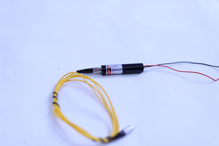
In the past, on the laser production line, the main tool relied on for online debugging was the power meter. According to the laser power, the debugging results of the spot size and the quality of the beam were judged. However, the power meter only reads the power and cannot intuitively reflect the changes in the beam with debugging. The debugging work is time-consuming and laborious, and it is difficult to ensure the consistency of debugging.
In order to improve the production efficiency of laser production lines, the famous German beam analyzer manufacturer CINOGY has specially designed a low-priced, small-sized, simple and practical online laser debugging beam analyzer - CinAlign for laser production line debugging. With the help of CinAlign's special beam analyzer for online laser debugging, windows can intuitively and quantitatively monitor the changes in power and spot at the same time, thus doubling the laser debugging time and greatly improving the consistency of the laser!
In addition, because the price of CinAlign online debugging beam analyzer is as low as 15,000 yuan, it can greatly reduce the cost of laser manufacturers. This is one of the reasons why CinAlign online debugging beam analyzer can be used in production lines in batches.
This article will introduce in detail the laser beam debugging method of the CinAlign online debugging beam analyzer based on the laser parameters that need to be debugged in the laser production line (spot size, power, energy distribution, divergence angle, etc.), coupled with software screenshots.
1. "CinAlign online debugging beam analyzer" can ensure the accuracy and consistency of each debugging:
1) Real-time monitoring of spot size
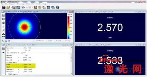
CinAlign online debugging and debugging beam analyzer software RayCi can monitor the spot size in real time, and we can know the laser spot size intuitively and quantitatively.
2) Spot size pass/fail setting
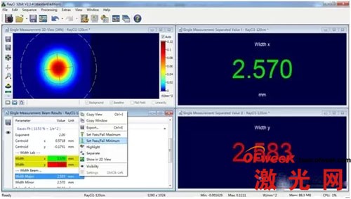
RayCi analysis software supports pass/fail setting of spot size. For example, during debugging, we need to control the spot size (X direction) between 300um~350um (that is, qualified product). Then we can set the spot size in the X direction on the software to be between 300um and 350um, which means pass (the software will mark the spot size in green), and when the spot size in the X direction is not between 300 and 350um, it will fail (the software will mark it in red). . Therefore, when production line personnel are debugging, they can only look at the change in spot color. The operation is very simple, it is easy for production line personnel to use it, and it can greatly save debugging time.
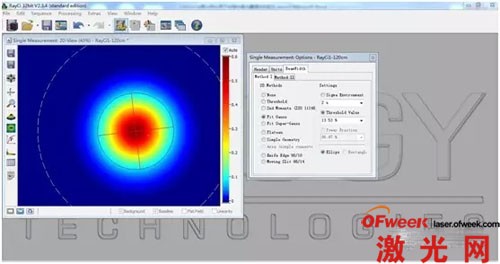
3) RayCi software can provide up to 10 spot size algorithms, which can basically fully meet the algorithm requirements of all customer applications.
2. Real-time monitoring of laser power:
1) Real-time monitoring of laser power. This function can not only replace the power meter, but also allow users to monitor the laser power and spot size at the same time during debugging.
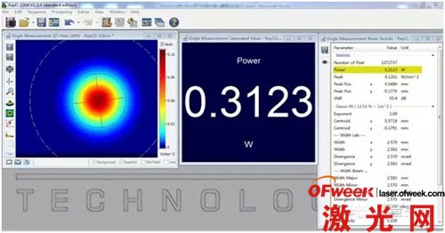
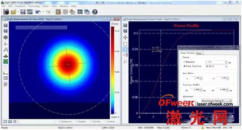
2) Give the power contour and calculate the spot size based on the power.
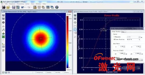
In some applications, customers need to know the spot size under different powers. The traditional debugging method using a power meter cannot realize this application, but CinAlign online debugging beam analyzer can solve this problem.
3. Real-time monitoring of changes in beam profile and beam ellipticity (roundness) for beam shaping:
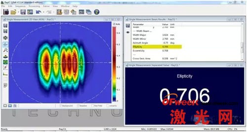
When shaping the beam, using the CinAlign online debugging beam analyzer, the user can very intuitively see the profile and ellipticity of the beam, so that it is very easy to debug to the required shape and size.
4. Real-time monitoring of changes in the position of the center of gravity of the beam (i.e. the coordinate system of the center of gravity), which can be used for laser alignment debugging or relative position debugging:
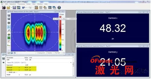
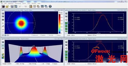
5. Real-time monitoring of the two-dimensional and three-dimensional energy distribution of the beam:
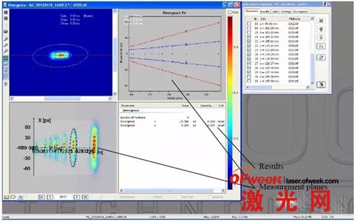
6. Measure the near field and original factory divergence angle:
1) Near field divergence angle measurement
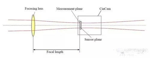
Df is the spot diameter at the focal plane, and f is the focal length.
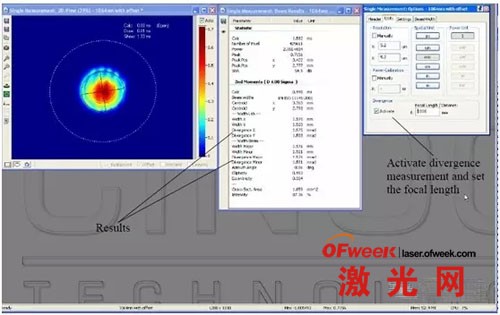
2) Far field divergence angle measurement

D1 and D2 are the light spot diameters at different positions, and L is the distance between the two measurement positions.
